Arrow VM1012-B Specifications Page 35
- Page / 49
- Table of contents
- BOOKMARKS

- 2.5L VM DIESEL 1
- ENGINE IDENTIFICATION 2
- DESCRIPTION AND OPERATION 2
- LUBRICATION SYSTEM 2
- DIAGNOSIS AND TESTING 3
- ENGINE DIAGNOSIS—PERFORMANCE 3
- SERVICE PROCEDURES 5
- CHECKING OIL LEVEL 5
- TIMING PROCEDURE 6
- VALVE AND SEAT REFACING 7
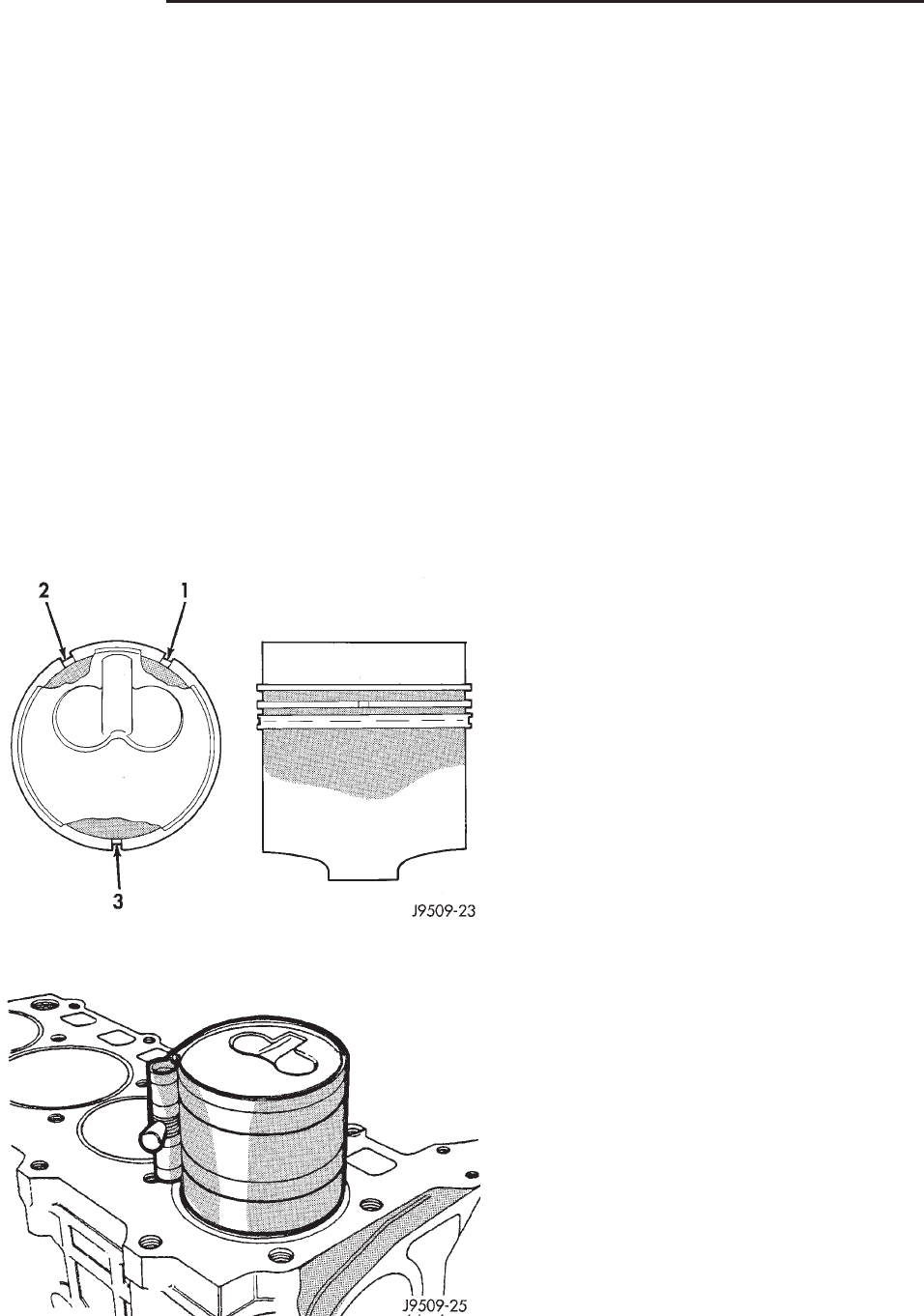
- FITTING PISTON RING 8
- CRANKSHAFT END PLAY 8
- REMOVAL AND INSTALLATION 9
- ENGINE MOUNT—FRONT 9
- ENGINE MOUNT—RIGHT 9
- MOUNT—LEFT SIDE 10
- ENGINE MOUNT—REAR 10
- ENGINE ASSEMBLY 11
- CYLINDER HEAD COVER 12
- ROCKER ARMS AND PUSH RODS 13
- CYLINDER HEAD 14
- 9 - 50 ENGINE NS/GS 15
- NS/GS ENGINE 9 - 51 16
- 9 - 52 ENGINE NS/GS 17
- HYDRAULIC TAPPETS 18
- VIBRATION DAMPER 19
- TIMING CHAIN COVER OIL SEAL 19
- INJECTION PUMP 19
- TIMING CHAIN COVER 20
- TIMING CHAIN 20
- 9 - 56 ENGINE NS/GS 21
- NS/GS ENGINE 9 - 57 22
- CRANKSHAFT SPROCKET 23
- HYDRAULIC TENSIONER 24
- CAMSHAFT 24
- CAMSHAFT BEARINGS 25
- CRANKSHAFT MAIN BEARINGS 25
- NS/GS ENGINE 9 - 61 26
- 9 - 62 ENGINE NS/GS 27
- OIL PUMP 28
- VACUUM PUMP 29
- NS/GS ENGINE 9 - 65 30
- 9 - 66 ENGINE NS/GS 31
- NS/GS ENGINE 9 - 67 32
- PISTONS AND CONNECTING ROD 33
- NS/GS ENGINE 9 - 69 34
- CYLINDER LINER 35
- CRANKSHAFT—REMOVAL 36
- REAR CRANKSHAFT OIL SEAL 36
- DISASSEMBLY AND ASSEMBLY 36
- CLEANING AND INSPECTION 37
- CYLINDER HEAD COVERS 37
- NS/GS ENGINE 9 - 73 38
- VALVES AND VALVE SPRINGS 39
- PISTON AND CONNECTING ROD 40
- CRANKSHAFT 41
- CRANKSHAFT MAIN BEARING 41
- SPECIFICATIONS 42
- 9 - 78 ENGINE NS/GS 43
- NS/GS ENGINE 9 - 79 44
- SPECIAL TOOLS 45
- NS/GS ENGINE 9 - 81 46
- 9 - 82 ENGINE NS/GS 47
- NS/GS ENGINE 9 - 83 48
- 9 - 84 ENGINE NS/GS 49
Related products and manuals for Engine Arrow VM1012-B
 (52 pages)
Samsung SI-M8W092BB1EU manuales
Manuales del propietario y guías del usuario para Tiras De Led Samsung SI-M8W092BB1EU.
Ofrecemos 1 manuales en pdf Samsung SI-M8W092BB1EU para descargar gratis por tipos de documentos: Ficha de datos

Samsung SI-M8W092BB1EU Ficha de datos (1 paginas)
Marca: Samsung | Categoria: LED strips | Tamaño: 0.38 MB |
Tabla de contenidos
Más productos y manuales para Tiras De Led Samsung
| Modelos | Tipo de documento |
|---|---|
| SI-L8T26115CEU |
Ficha de datos
Samsung SI-L8R20115CEU LED lamp,
9 paginas
|
| SI-A8W052181EU |
Ficha de datos
Samsung CLASSIC B35 E14 5.2W,
2 paginas
|
| SI-M8W042AD1EU |
Ficha de datos
Samsung GU5.3 MR16 3.2W,
1 paginas
|
| SI-L8V32115CEU |
Ficha de datos
Samsung G13 30W 1500mm,
1 paginas
|
| SI-M8V062AD1EU |
Ficha de datos
Samsung MR16 GU5.3 3000K 12V 5.8W,
2 paginas
|
| SI-P8W163BB1EU |
Ficha de datos
Samsung E27 PAR30 15W dim.,
1 paginas
|
| SI-M8V042BB1EU |
Ficha de datos
Samsung GU10 PAR16 3.3W,
1 paginas
|
| SI-M8W073BD1EU |
Ficha de datos
Samsung GU10 PAR16 7.5W dim.,
1 paginas
|
| SI-M8V042BD1EU |
Ficha de datos
Samsung GU10 PAR16 3.3W,
1 paginas
|
| SI-M8V085AB1EU |
Ficha de datos
Samsung GU5.3 MR16 7W,
1 paginas
|
| SI-P8W151HB1EU |
Ficha de datos
Samsung G53 AR111 15W dim.,
1 paginas
|
| SI-A8W052140EU |
Ficha de datos
Samsung SI-A8W052140EU LED lamp,
1 paginas
|
| SI-M8V072BB1EU |
Ficha de datos
Samsung PAR16 GU10 3000K 230V 6.5W,
2 paginas
|
| SI-A8W052180EU |
Ficha de datos
Samsung CLASSIC B35 E14 5.2W,
2 paginas
|
| SI-M8V042AB1EU |
Ficha de datos
Samsung GU5.3 MR16 3.2W,
1 paginas
|
| SI-M9W085AB1EU |
Ficha de datos
Samsung GU5.3 MR16 7.5W,
1 paginas
|
| SI-M8W062AD1EU |
Ficha de datos
Samsung MR16 5.8W,
2 paginas
|
| SI-P8W151HD1EU |
Ficha de datos
Samsung G53 AR111 15W dim.,
1 paginas
|
| SI-M8W085AD1EU |
Ficha de datos
Samsung GU5.3 MR16 7W dim.,
1 paginas
|
| SI-M8T062AB1EU |
Ficha de datos
Samsung MR16 5.8W 4000K,
2 paginas
|
© 2020, manymanuals.com. All rights reserved. | 0.013 s |
 Manymanuals.com
 Manymanuals.de
 Manymanuals.fr
 Manymanuals.it
 Manymanuals.pl
 Manymanuals.cz
 Manymanuals.es
 Manymanuals-pt.com
Comments to this Manuals